
25 Dec. 2007

To make a complete analyze of the drive system, it is necessary to study the mutual influence between its parts , those parts are:
1-Motor ( AC motor)
2-Frequency converter
3- Network supply
Mainly, in all applications of frequency converters , it is known that there is a negative impact on the network when frequency converter is connected to it, and there is standards in Europe to regulate that negative impact included in EN 61000-6-3 directive for using electrical equipment in residential, commercial and light industry environment, EN61000-6-2 in industrial environment.EN60601-1-2 in hospitals.
For this reason it is necessary to include EMC filter in the drive system, that filter can be added between the drive and the connection point to the network ( mainly , all drives manufacturers must to do that) or to have it built in the drive as NFO Drives AB does
AC Motor
The motor could be old (used) as in retrofitting projects or new as in any project will be planned .In new project ,the motor could be chosen standard type or inverter duty type.
The inverter duty type motor is constructed to withstand voltage spikes up to approximately 2 times its nominal DC voltage say 1130V for nominal AC voltage 400V .
Frequency converter could be PWM type converter ,PWM type + patched solution as (dV/dT filter, Sine wave filter or sine wave former) or NFO Sinus Inverter
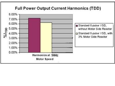
Character of wave form on the output of PWM type Frequency converter
PWM- FC has a wave form that appears as a choppy squared-off wave when viewed through an oscilloscope . Such output voltage , will be a source of harmonics currents as it is shown on the following fig.

 Positive sequence harmonics (7,13,19,25 etc.) create a magnetic field in the direction of rotation. The magnetic field developed by the fundamental harmonic (50 Hz) must be in the direction of rotation. Otherwise, the motor would run backwards. Therefore, the fundamental is a positive sequence harmonic. Negative sequence harmonics(5,11,17 ,23 etc.) develop magnetic fields in the opposite direction of rotation. This reduces torque and increases the overall current demand required for a given load.
The presence of harmonics in the output voltage of frequency converter results in excessive heat of the AC motor. A load designed to pull 25 amps at full load may draw 30 amps if the harmonic distortion is high. This additional current can lead to insulation damage and possibly a catastrophic failure
http://www.pdma.com/VFDtest.html
For example, the 5 th harmonic , is consuming electrical energy and wasting it as a heat in the motor with out giving any useful work, the system needs to consume more energy to balance its negative effect as the 5 th harmonic is trying to rotate the motors shaft in the opposite direction of the motors movement.
Negative effect of harmonics in the output signal of frequency converter
1- Motor heat , vibration and noise – short motor life
2-Common mode current
-Bearing currents .
-Instrumentation reference to ground
3- Torque ripple
Negative effect of pulse wave form in the output signal of frequency converter
1- Voltage wave reflection in long cables ( above 25-35 m)
That’s extremely important to be avoided in applications like :
- HVAC systems , heating, ventilation and air conditioning
- elevators
- Pumps
- Traction and conveyer systems
- Low voltage regulated power supply to medium voltage motor.
- Test floor and test stand applications.
- Shore to ship power for non-50 Hz systems.
Matching Frequency converter with AC electric motor
1- conventional PWM type F.C with used motor
Reflective wave between the PWM type F.C and the motor ( high dV/dT) in additional to harmonics content will damage the motor.
High dV/dT Effects
The rapid rate of voltage rise (dv/dt) at the leading edges of each output pulse of the PWM inverter, produces an uneven distribution of voltage within the motor windings. The result is a concentration of the voltage at the particular points of the winding causing abnormal stress leading to breakdown of the insulation. This phenomena has been described as "first coil breakdown" and is well documented.
Reflections in Long Lines & Cables
A long cable, in addition to resistance, has distributed inductance and capacitance, producing effects similar to a transmission line .
The high frequencies present in the output of PWM wave forms cause reflections in long conductors connecting the motors to the drives . Harmful effects with conductors as short as 10 meters have been observed. However, the effects are most severe with cables of lengths greater than 50 meters leading to the doubling of the applied voltage. This translates to voltage peaks approaching 1130 volts in 400 volt systems.
Cable Input & Output Voltage - Using No Filter
On the output of PWM inverters the voltage peak due to reflections in long cable lines can be 200% ofthe DC bus voltage value..
The combination of these two effects stresses the winding insulation considerably beyond design limits and has been known to shorten the insulation life and in some instances leads to early catastrophic failure of motors.
Possible solutions :
To add ( dV/dT) on the out put of the PWM type F.C or/and to derate the motor , either else , to get less work from the motor .
What’s wrong with such solution?
-The filter(reactor) seems to be that it will protect the motor from the high speed rise of the voltage ( high dv/dt), but the voltage value ( surge voltage) will continue to stress the motors windings with a fraction of the duoble DC voltage ( say 1130 V for 400 AC voltage), the reactor will limit the speed range regulation of the AC motor, applying vector control with feed back will be more complicated .More investment and more losses.
 - The harmonics content, will continue to reflect its negative impact (as mentioned above) on the motor as heating ,vibration , noise , possible bearing damage and less efficiency.

 For centrifugal fans and pumps , even a minor change in motors operating speed translates into a significant change in imposed load and annual energy consumption. Fan and pump “affinity” laws indicate that the power loading upon a motor by centrifugal loads varies as the third power or cube of its rotational speed. For example a seemingly minor 20rpm increase in motors rotational speed from 1450 to 1470 rpm .- can result in 3.8% increase in the load placed upon a motor driving a fan or a pump. In contrast, the quantity of air or water delivered varies linearly with speed .
 http://www1.eere.energy.gov/industry/bestpractices/pdfs/mc-2463.pdf
Fans exhibit the best savings for the reasons shown:
1-In variable speed drive (VSD) systems, Volume is proportional to speed, while power is a function of speed cubed
2-Thus for half volume, we need half speed and one eighth power
3-Significant noise reduction is another strong benefit in many systems
Calculation example for 15 kW derated motor to 9 kW
If the (used) derated 15 kW motor will run with 17 A( rated current for 9 kW motor) its speed will be about 2960 rpm. In the same situation for 9 kW motor , it will run with rated speed 2949 rpm . the difference in speed rotation can be translated to 2.5 % energy consumption
Please see motors data used for calculation.
http://www.transdrive.co.uk/leroy_somer_2pole_selection_chart.htm
As shown above , derating the motor in retrofitting project and using patched solution like dV/dT filter to protect the standard motor will cost more money and reflects in less reliability . The best solution in this case is to feed the used motor with pure sine wave current and voltage without any derating , This solution is real and could be found by using NFO Sinus Inverter.
1- Conventional PWM – FC with new standard motor in new project
In this case , it is necessary to derate the motor and to add output filter(dV/dT) , or to use sine wave former on the out put of PWM-FC without derating of the standard motor.
 Please take a look on the following link:
http://pdf.directindustry.com/pdf/mte/mte-corporation-catalog/17137-27790.html
 From easy calculation, its clear that such patched solution is more expensive and less reliable than using NFO Sinus F.C with pure sine output waves forms signals.
Below is shown an example of price level for such solution :

 For 15 kW motor, adding sine wave former will consume additional 650W in every hour of its work !!( about 850 USD/ year)
In addition , using sine wave former will limit the speed range and make it more complicated to apply Vector control .
Typical relative costs-Drive and preventative measures ( Motor = 100%)

Reference:http://www.gambica.org.uk/pdfs/Report1_3rd%20Edition.pdf
1- Using conventional PWM-F।C with inverters duty motor
In this case, there is no need for oversizing the motor , no need for dV/dT filter , but the PWM – FC still continue to deliver square waves form output signals to the motor, and include harmonics content, which will be reflected in heat losses equal to (5-8) % as wasted energy of the motors power rating .
Other wise , it needs to apply patched solution and to add Sine Wave Former, which means, that the same shown above calculation will be applied !!
At NFO Drives AB , we have the right solution , 

 A small additional capital investment in NFO Sinus Inverter means :
1- Elimination of motor overheating, vibration and noise ( increase motor life)
2- Elimination of harmonic content on the output of NFO sinus ( pure sine wave) ,no losses ,no need for output filters
3- No oversizing of old (used) or new standard AC motor.
4-Elimination of voltage wave reflection ,no voltage spikes in the output of NFO Sinus Inverter (no need for dV/dT filter)
5- No bearing currents ( we give 5 years guarantee for any new motor)
6- Elimination of torque ripple.
7 – Elimination of instrumentation reference to ground. ( RSD or earth leakage protection)
8-Economic solution to protect the motor and save electric energy.
Conclusion.
It is a fact that PWM- FC s can damage the insulation system of your motor. However, with better understanding, you should be able to prevent the infant mortality that so many have seen. Unless you’re looking for a reason to replace the motor, you should not install a PWM FC to an aged class B insulation system. Drive manufacturers of PWM- FC have increased effectiveness through PWM technology to deliver close to a clean current waveform to your motor. But that current comes with the expense of very fast rise time (dV/dT) and harmonics content.
Looking for a patched solution by adding sine wave output filter will protect the motor , but it will result in more capital investment and continuous additional consumption of electric energy , which could cost, in one year, more than 35% of the total purchasing price of the drive.
To avoid all above mentioned headaches and to save your money , NFO Drives AB offer you the solution by using NFO Sinus F. C and the particular, expensive part in it is the (NFO Sinus- Switch) which delivers a clean sine(pure sine wave form) voltage to your motor.
Weather your project is new or retrofitting type , your motor premium or standard one . In all cases with NFO Sinus F.C , your application will work in perfect way for long time with minimum preventive maintenance and saving your money and effort !!
